Summary
In this report arithmetical representations are suggested for measuring rotational speed and cycle difference of speed sensors. The suggested arithmetical representations are used in parameter maximization and gear wheel blueprint of Hall Effect rotational speed detectors and measuring methods. Experiment outcomes indicate that the mathematical representations are very important and valuable for the design and measurement of rotational speed sensors.
Introduction
Rotational speed sensors and mathematical models are broadly utilized in industrial machines, production systems, robots and automotive sector for measuring, monitoring and controlling generators, motors, spindles of various rotating instruments.
There are many rotational speed determining techniques. The most commonly utilized techniques are rotational signal counting techniques utilizing proximity switches, programmers and gear tooth sensors (Hernandez 407; Kirianaki 427; Liu and Zhe 84). Such devices have a comparative high resolution. Their demerits are costly and small frequency spectrum. A further sensor built-in the encoder is required for sensing the direction of rotation (Hernandez 405; Johnson 26).
Rotating speed detectors function based on certain standards. Such detectors utilize a metal gear in order that they are simple and inexpensive for industrial uses. Therefore the sensors find increasing uses in industrial sector. However, basic study of gear tooth speed detectors with dual yields is still incomplete until now.
This report describes arithmetical equations for measuring the metrics of rotating speed detectors. The suggested arithmetical representations are used in Hall Effect detector (Liu and Zhe 85). Experiment outcomes indicate that the mathematical representations are very important and valuable for the parameter maximization, design and application of rotational speed detecting devices.
The first section of this paper gives mathematical models. The second part gives the experiment results, measuring systems, phase drift between the impulse outputs and duty cycle of the impulse outcomes. The third part gives applications of the sensors. The last part of this report gives the conclusions drawn from this study.
Arithmetical Representations
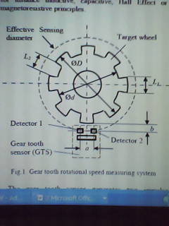
As indicated in figure 1, two sensors separated by a distance, a, are integrated in the detector. The sensors detect the rider of the target wheel consistent with various physical standards, for example capacitive, Hall Effect, inductive standards.
The detector produces dual signal yields with a phase difference, ∆Φ when the sensor faces the rider of the gear. Through calculation of the number of impulses per output, n, within a given time, t, the rotational speed, ω, can be calculated by
(1) ω=n/tN (rps),
or (2) ω=60n/tN (rpm)
With “N” as the number of teeth of the target wheel, “T” as the time period and “f” as the frequency of impulse is determined by
(3) f=n/t=ωN (Hz),
and (4) T=t/n=1/ωN (s)
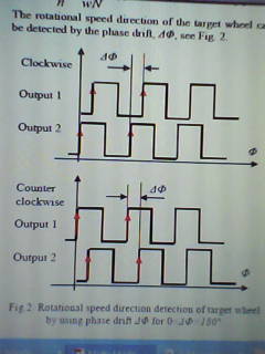
The direction of rotation of the target wheel can be sensed by the phase shift, ∆Φ, as shown in figure 2.
∆Φ for 0< ∆Φ >180°
The phase shift, ∆Φ, between the two impulse yields depends on the distance between the two sensors, a, the external diameter of the wheel, D, the detecting distance between the rider of the wheel and the sensors, b, and the number of teeth, N.
The phase shift can be determined by ∆Φ=Φ2 (Output2) – Φ1 (Output1)
(5) (360°N)/π * sin-1*((→a)/√((D+2b)2+a2))
Where the distance vector, →a is described as follows: (6)
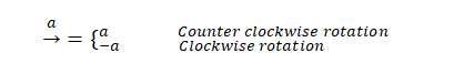
One can obtain the phase shift ∆Φ>0 for anticlockwise rotation and ∆Φ<0 for clockwise replacement of the target wheel given that 0< ∆Φ<180°. The duty cycle of the impulse outputs, η, is useful for a number of uses and can be calculated by
(7) η=(δL1)/L=(δL1 N)/(π√((D+2b)2+a2))
With δ as net effect determinant, L1, as rider arc width and L as tooth pitch, which is defined as follows:
(8) L=π/N √((D+2b)2+a2)
The net effect determinant, δ, depends on the nature and size of the wheel and can be defined through testing. In the most uses the requirement, D+2b≫a, is easy to achieve. In this case the duty cycle and phase difference can be simplified as
(9) ∆Φ=(360°a)/L=(360°aN)/π(D+2b)
(10) η=(δL1)/L=(δL1N)/(π(D+2b))
with (11) L=π/N*(D+2b)
The shift difference, ΔΦ, is directly proportional to the distance vector, a, and the number of teeth, N, and is indirectly proportional to the external diameter of the wheel, D, and the detecting distance, b. The rider width, L1, increases with the duty cycle, η, and the number of teeth N, and decreases with the external diameter, D, and the distance of detection, b. For wheel with a comparative large external diameter under the requirement D≫b, the above metrics are estimated to:
(12) ∆Φ=(360°a)/Lg=(360°aN)/πD
(13) η=(δL1)/Lg=δηg=(δL1N)/πD
with (14) Lg=π*D/N=L1+L2, as geometric tooth arc pitch,
and (15) ηg=L1/Lg=(L1N)/πD=L1/(L1+L1), as geometric duty cycle of the target wheel.
In such a case, the phase difference and cycle depends simply on geometric metrics L1, L2 and the separation between the two sensors, a. One can utilize such expressions to design the wheel comparative easily (Hernandez 66; “Allegro Micro Systems” par. 3).
Experiment results
Measuring method
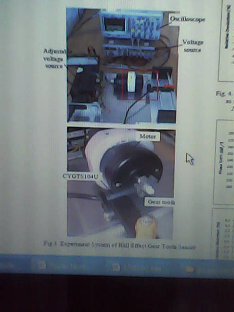
Appendix I indicates a model system of Hall Effect gear tooth detectors. The Hall Effect detector is CYGTS104U with 2 signal yields (Liu and Zhe 84; Liu par. 4) and senses the speed of rotation of the direct current motor. The separation between the 2 sensors is 5.4mm, i.e. a=5.4mm. The oscilloscope is utilized to test the signal yields of the detector, so as to determine the phase difference and the duty cycle of the final impulses.
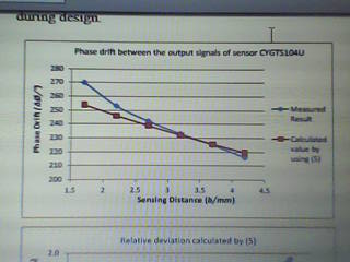
Phase difference between the signal yields
Figure 4 shows the measured phase difference between the 2 signal yields of the detector CYGTS104U in association with the value determined by the experiment system. It is not more than ±3% in detecting distance range from 2.1 – 4.5mm. Thus the model can be utilized for approximating the phase difference of final impulses of rotational measuring devices during design.
Impulse outputs
The impulse outputs of one final impulse of the detector are indicated below (see table 1). All utilized wheels have 6 teeth and external diameter of 28 mm, and diverse arithmetical impulses (Pallas-Areny 28; Pascal and Friz 37).
Table 1: Impulse outputs as function of detecting distance (b) and arithmetical shift (ηg)
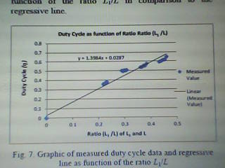
Utilizing these measured values one can formulate a regressive linear expression:
(16) η=1.3984 L1/L+0.0287
Figure 4 illustrates the graphic of measured values as function of L1/L in relation to the regressive trend.
The mathematical model (16) can be simplified to
(17) η=(1.3984+0.0287L/L1)*L1/L
Comparing the mathematical model (17) to (10) one can obtain the net effect determinant δ roughly:
(18) δ=1.3984+0.0287L/L1
Hypothetically the relationship L1/L varies in the range 0<L1/L<1. One can utilize the value L1/L=0.5 for determination of the net effect determinant δ. Thus the net effect determinant δ is calculated as follows:
δ=1.3984+0.0287/0.5=1.4558
By use of the metric δ=1.4558 the duty phase can be determined by equation (7). Taking the gear wheel with ηg=0.5, D=28mm and L1=7.34mm as example the hypothetical duty phase η is determined based on equation (10). Figure 5 gives the outcomes.
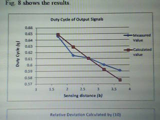
The relative drift between the computed and measured values is a function of the detecting distance. It is not more than ±3% in detecting distance range from 1.70mm to 3.70mm. Thus the equations (7) and (10) can be utilized for approximating the output impulses of rotational measuring devices during design (Patrascoiu and Sochirca 169; Papoulis 35).
Applications
The arithmetical representations can be utilized for design of the wheel of gear tooth detectors with dual yields and rotational speed detecting devices. Taking the requirement D+2b≫a as example, the duty cycle and cycle difference can be defined by (9). In this situation, if the external diameter, D, the distances, a and b, are given the value of N can be calculated by
(19) N=π(D+2b)/(360°a)*∆∅,
and the rider arc width L1 can be calculated as follows
(20) L1=(π(D+2b))/δN*η
So as to obtain an appropriate duty cycle η=0.5 and a phase difference Δϕ=90° for a rotational speed measuring sensor the recommended rider arc value L1 and the number of teeth N should be calculated as follows
(21) N=π(D+2b)/4a,
and (22) L1=(π(D+2b))/2δN
In relation to (11) the arc pitch L should be at least 4 times of separation between the 2 sensors, i.e. L=4a (Liu and Zhe 85). The arithmetical curve size Lg is equivalent to 17.59mm based on (14). Similarly one can as well calculate the external diameter, D, of the gear wheel and the detecting distance, b.
Conclusions
Based on the test outcomes one can conclude that:
- The difference between the two outputs can be calculated by use of the representations (4) and (9). The comparative variation of the metric determination is within ±3%.
- The net effect determinant δ of the gear wheel can be approximated by linear equation by use of the measuring values of duty cycles of the dual outputs at various arithmetical duty cycle of the gear wheel.
- The geometric equations suggested in this report can be used for calculating the metrics of the gear wheel and other metrics of the rotational speed sensing devices.
- The representations are very practical for evaluating gear tooth detectors with two output signals and very effective and supportive for the design and analysis of rotational speed sensing devices.
The additional studies should be focused on the model-oriented development of the rotational speed detectors and measuring devices so as to maximize the measuring device and save the development period and costs.
Works Cited
“Allegro Micro Systems, Inc.: ATS617LSG, Dynamic, Self-Calibrating, Peak-Detecting, Differential Hall Effect Gear Tooth Sensor IC.” Data Sheet (2010): n.pag. Web.
Hernandez, Wilmar. “Improving the response of a wheel speed sensor by using frequency-domain adaptive filtering.” IEEE Sensors Journal 3 (2003): 404-413. Print.
Hernandez, Wilmar. “Improving the Response of Wheel Speed Sensors by using Robust and Optimal Signal Processing Techniques.” IEEE International Symposium on Industrial Electronics 4 (2005): 403-416. Print.
Hernandez, Wilmar. “Improving the Response of a Wheel Speed Sensor by Using a RLS Lattice Algorithm.” Sensors 6 (2006): 64-79. Print.
Johnson, Charles. Process Control Instrumentation Technology. 5th ed. 1997. Upper Saddle River, New Jersey: Prentice-Hall. Print.
Kirianaki, Yurish. “High Precision Wide Speed Range Rotation Sensing with UFDC-1.” Sensors & Transducers Magazine 59.9 (2005): 426-431. Print.
Liu, Ji-Gou and Zheng Zhe. “Mathematical Models of Gear Tooth Speed Sensors with dual outputs.” Joint International Symposium: proceedings of a Conference Held 2011 at Germany. Canberra: Department of Technology, 2011. 82 – 86. Print.
Liu, Ji-Gou. “Hall Effect Gear Tooth Sensors CYGTS104.” Data Sheet, ChenYang Technologies GmbH and Co. KG (2009): n.pag. Web.
Pallás-Areny, Webster. Sensors and Signal Conditioning. 2nd ed. 2001. New York: John Wiley & Sons. Print.
Papoulis, Pillai. Probability, Random Variables, and Stochastic Processes. 4th ed. 2001. New York: McGraw-Hill. Print.
Pascal, Desbiolles and Achim Friz. “Development of High Resolution Sensor Element MPS40S and Dual Track Magnetic Encoder for Rotational Speed and Position Measurement.” Technical Review 75.1 (2007): 36-41. Print.
Patrascoiu, Poanta and Tomus Sochirca. “Virtual Instrumentation used for Displacement and Angular Speed Measurements.” International Journal of Circuits, Systems and Signal Processing 2.5 (2011): 168-175. Print.
Appendix